SCeye® | Process monitoring for laser welding and laser brazing
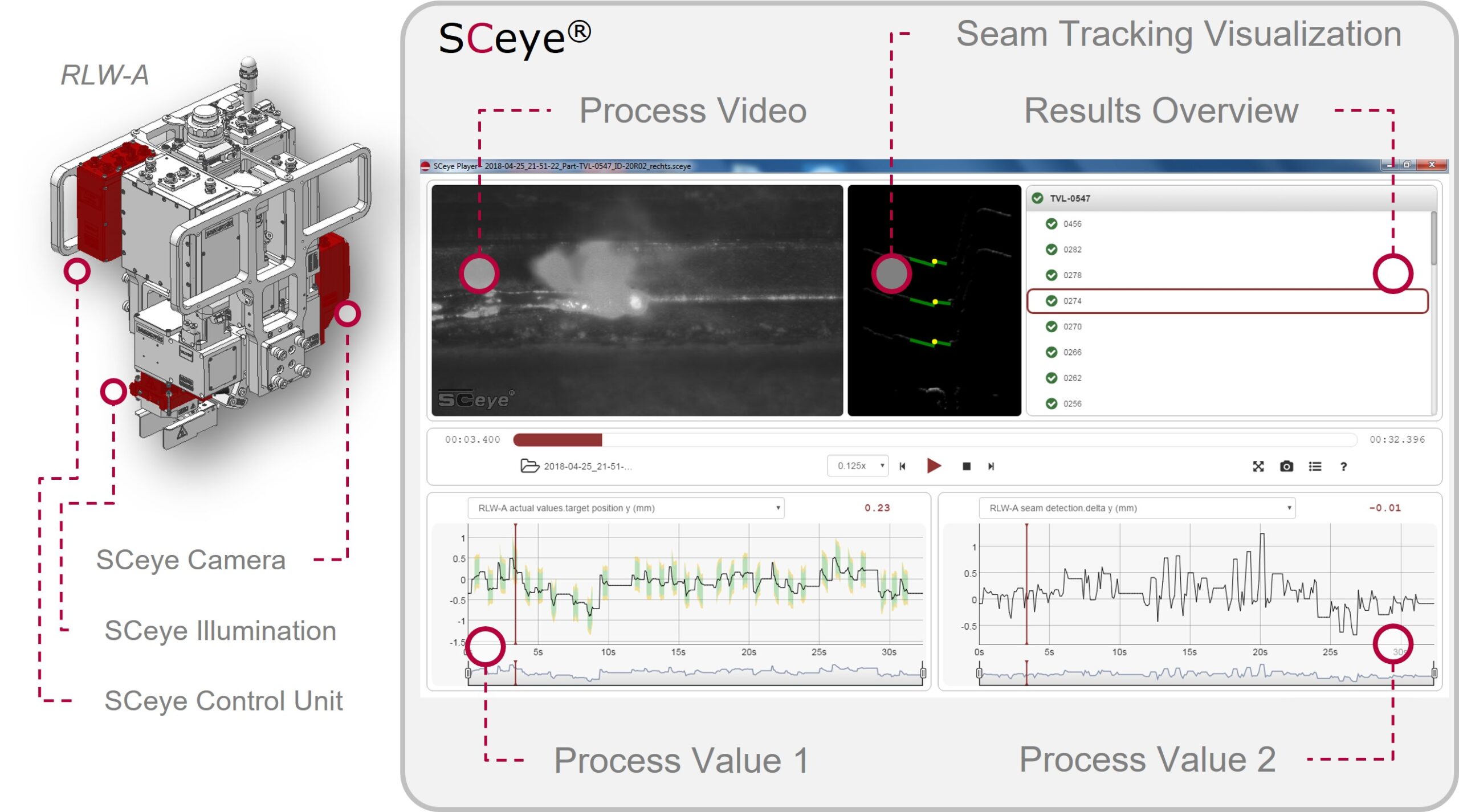
SCeye is an imaging process monitoring system, consisting of a coaxially integrated camera and a process lighting.
Function description
Benefits
- Fully integrated in Optics
- Coaxially integrated camera and illumination module
- Integrated recording and control unit
- Powerful evaluation electronics for real-time image processing
- Integration into existing optics
Sustainable hardware
SCeye’s hardware is designed to keep up with the latest state of the art technology for many years and to increase productivity and customer benefits through new updates and features such as wire recognition, speed monitoring or quality control.
Synchronized recording of image and process data
The following data are recorded
- Image information from the process zone
- Parameters of the laser opticsk
- Fieldbus signals for controlling the optics (digital switching signals)
Further process parameters which are communicated via the fieldbus. These can be freely configured by the customer. Typical signals are:
- Laser power
- Robot speed
- Wire feed rate
- Gas flow
Simple operability
Intuitive operation is made possible by an easy-to-use web GUI.
Reduced set-up time
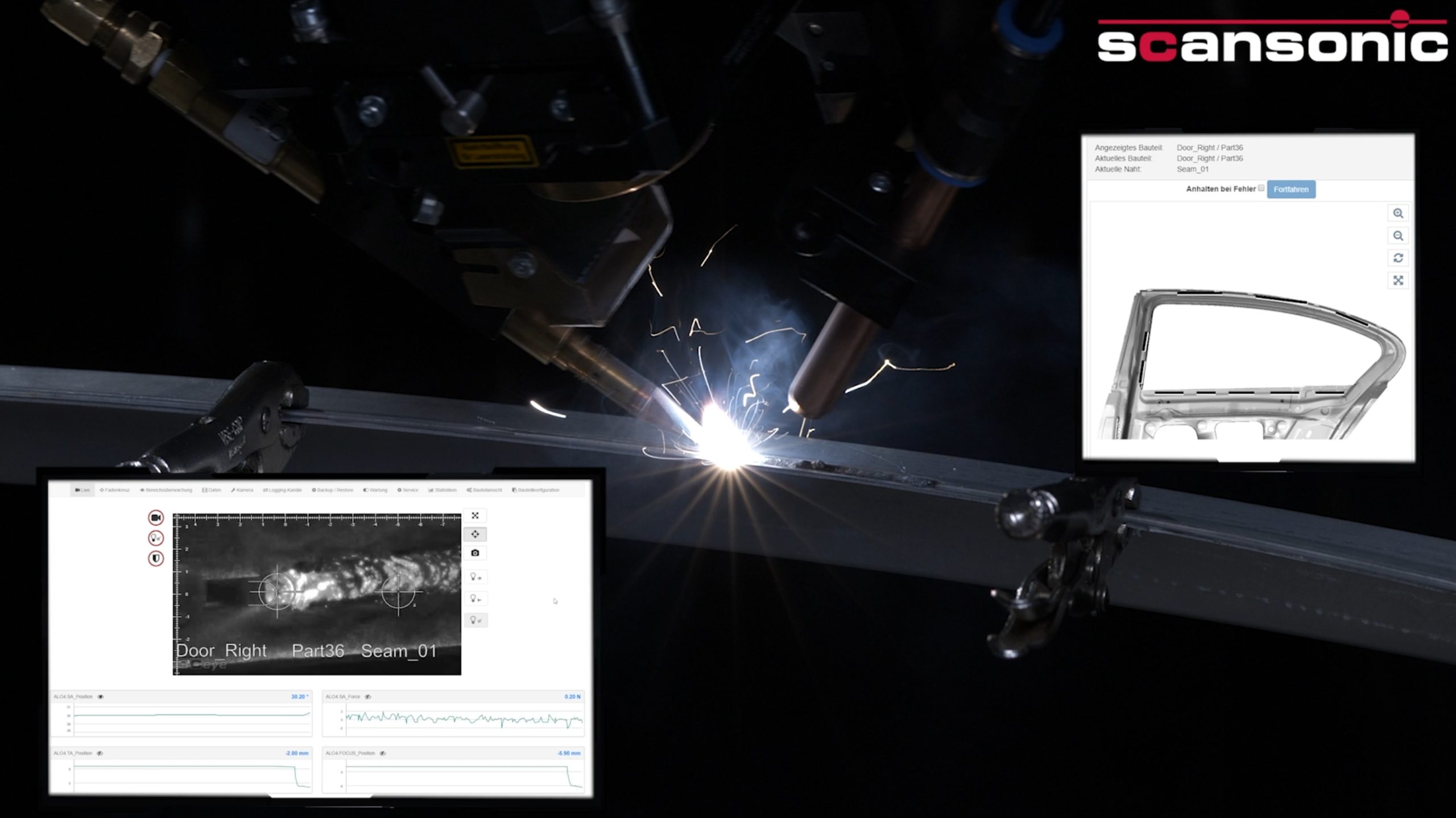
- Live view of the process zone is ideal for setting up the process and teaching the robot path.
- Live display of parameters of the optics or feedback on parameters, forces and positions
o Swivel axis position (SA_POS)
o Force on the swivel axis (SA_FORCE)
o Deflection of the telescopic arm (TA_POS)
o Deflection of the autofocus (LA_POS
In the live view, the operator receives direct feedback from the process zone. The visualization of the process zone shows exactly if the wire is in the right position and meets the joint.
Through the live display of the optics’ parameters, discontinuities in path programming or process control during the setup phase can be detected and optimized.
During the set-up process, a laser class 1 LED lighting of is switched on.
Live view during the laser process
During the laser process, the system switches to class 4 laser illumination. This means that the intensive process lighting can be overshadowed. This ensures a good visualization of the process zone at all times.
Freely configurable markings enable continuous checking of the beam-wire position during the process.
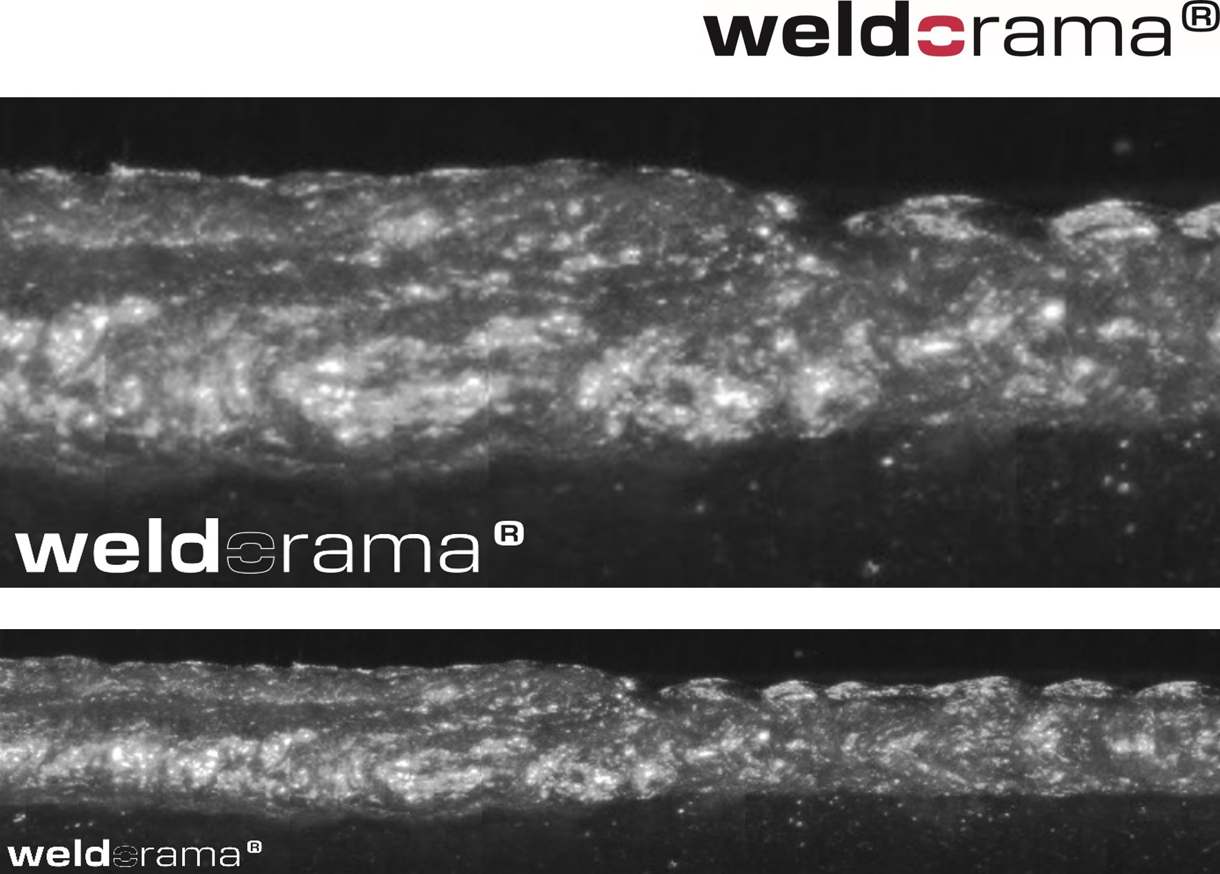
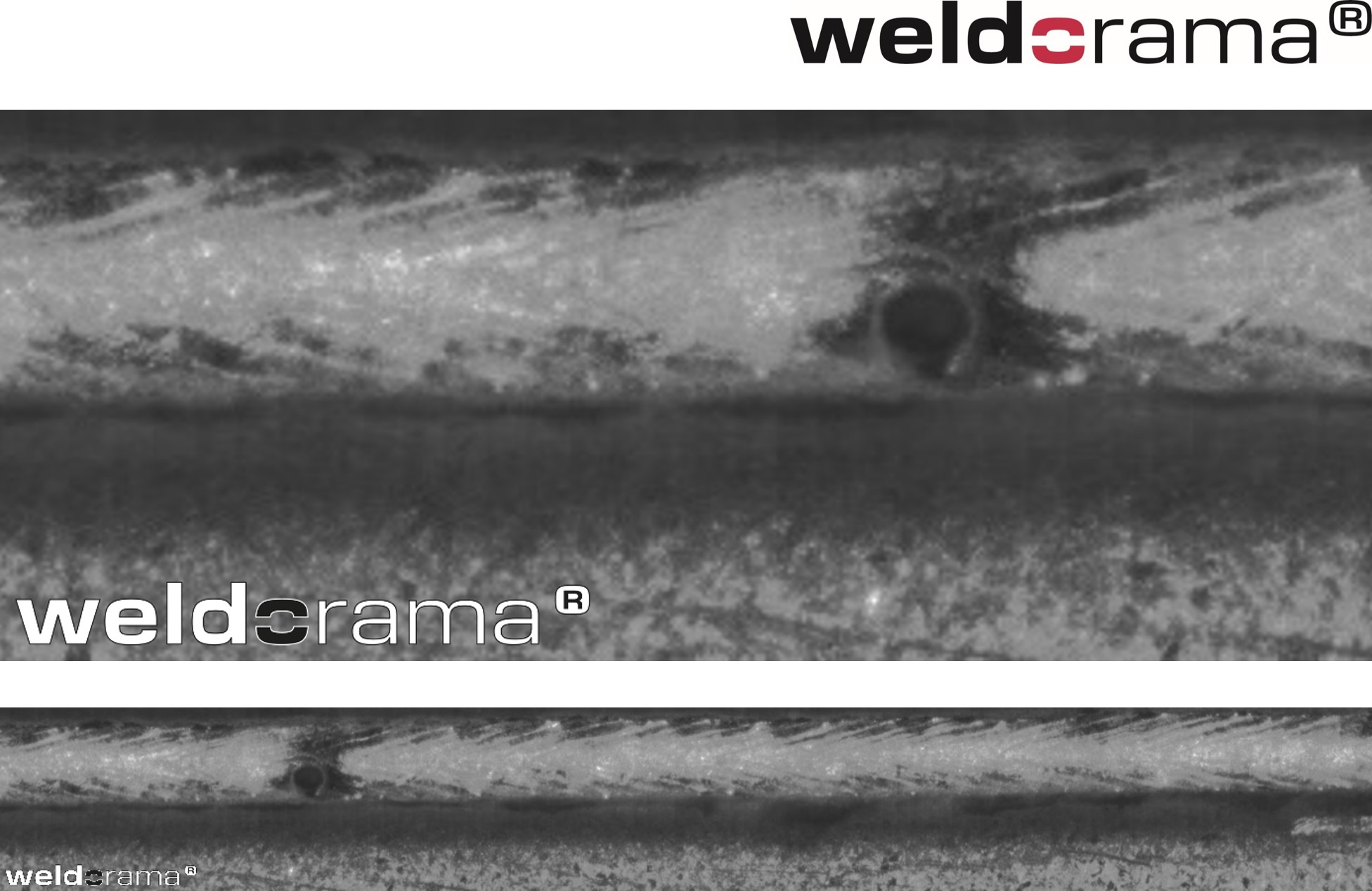
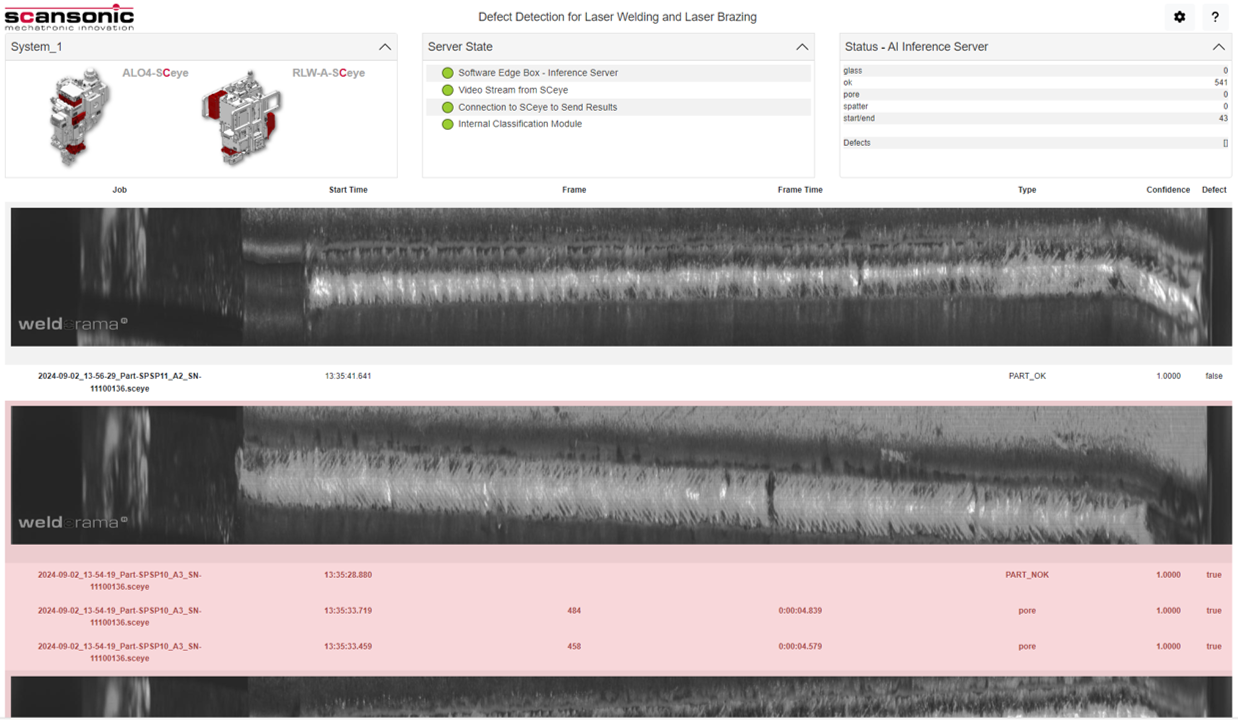
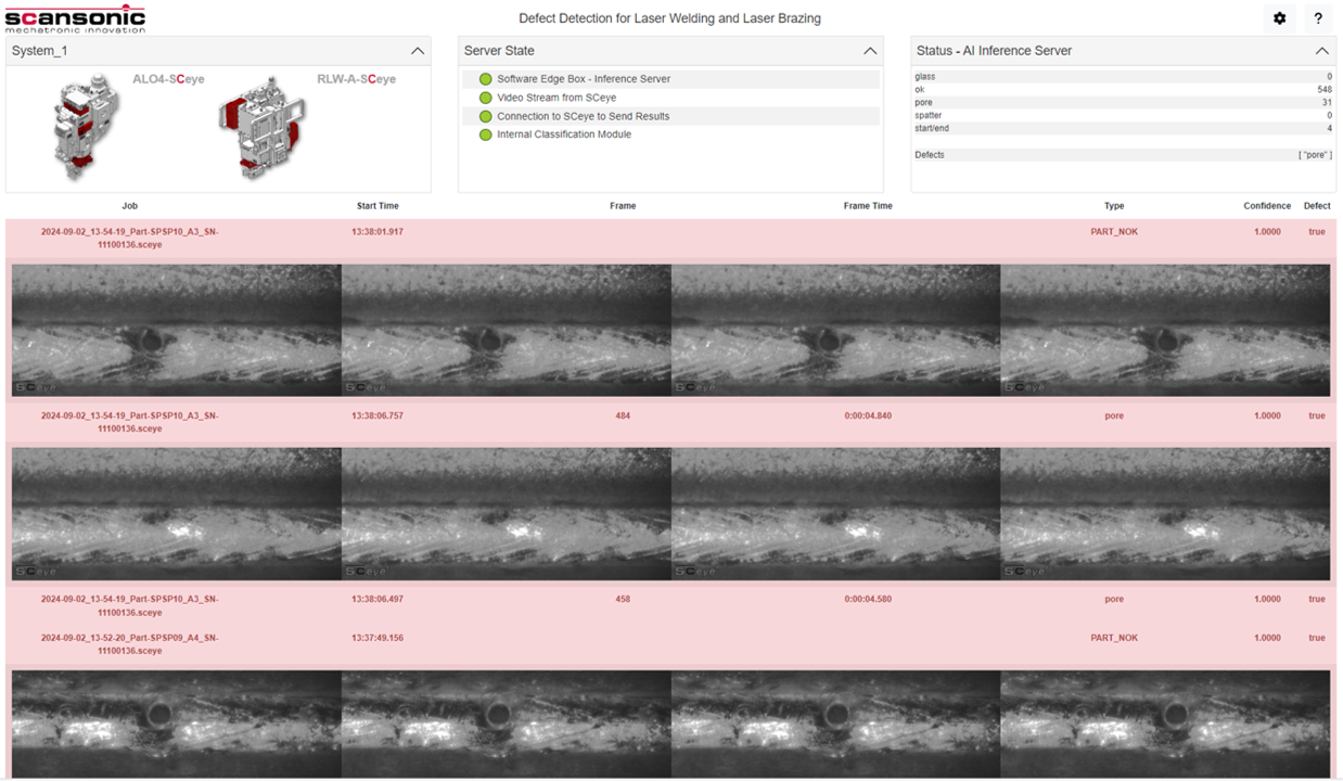
Increased process understanding and fast failure analysis through off-line analysis
Through manual analysis of the image information, errors can be quickly analyzed and their cause eliminated. Timing problems can lead to undesirable effects, especially at the start and end of the process. The visualization of the process zone by SCeye enables the operator to check whether the interaction of wire feeding and laser-on-time is optimally coordinated.
In addition, the video material provides information about the causes of a failure occurrence.
SCeye player is able to show the image material with the recorded process and optics’ parameters synchronized with each other.
Increased productivity
- Quicker troubleshooting due to synchronized data recording and high-speed video
- Damage avoidance of clamping devices by range control of swivel axis
- Increased process understanding during the process start-up phase
Worldwide availability
All SCeye® features including Weldorama® are available for a wide range of Scansonic optics. Get in touch with our sales and service contacts (Europe, Asia, Australia, Africa and America, including the US).
Further product information
Camera System
| Sensor | CMOS |
| Frame rate | 100 fps |
| Field of view | ~ 8 x 15 mm |
| Interface to ALO3 | Power supply, field bus, internal control bus |
Illumination System
| Integration | coaxially, fully embedded |
| Process illumination | 2x VCSEL, gepulst |
| Laser class of process illumination | class 4 / 860 nm / max. 16 W |
| Setup illumination | 2x LED (eye safe) |
Data Processing
| Data recording and analysis | fully embedded |
| Internal memory | ring buffer for min. 8h processing time |
| Recorded data (with 100hz) | images SA_pos, SA_force, TA_pos, LA_pos; seam no./ part no. / serial no. other field bus signals |
| Output signals (fi eld bus) | warn and fail signals / part ok / seam ok |
| Data transmission | Ethernet (instead of HMI-cable) |
Contact us
Sales
Sales & Customer Support
phone +49 - 30 - 91 20 74-346
fax +49 - 30 - 91 20 74-333
e-mail sales@scansonic.de
Service
Technical Service
phone +49 - 30 - 91 20 74-311
Mon - Sun 8 a.m. - 4 p.m. (Sat/Sun for emergencies)
fax +49 - 30 - 91 20 74-333
e-mail service@scansonic.de